Archive for March, 2008

Motor Install Attempt #2

March 31, 2008

Motor Installed

Battery PlacementModified Radiator Mount

For this install attempt I removed the driveshaft from the differential and slid it into the tail shaft before lowering it into place, keeping the oil sealed in the transmission. It was then bolted into the original transmission mounts. Because the motor mount it not fabricated yet it is resting on a jack for proper placement and is still attached to the shop crane as a safety consideration (should it slip off the jack). The radiator mount was also cut to accommodate the front batteries. Next step will be to the purchase steel needed to fabricate the battery hold downs.

Motor Prep

March 31, 2008

Things didn’t go totally according to plan. I filled the transmission with a synthetic oil to replace the old gunky oil that was drained. Unfortunately this was so much less viscous that what was previously a slow dribble of oil when the transmission was tilted to remove it became a steady flow of the 1.7L freshly filled and the lowering attempt had to be aborted before it lost more than the .3L of oil I had remaining could replace.

Adapter Plate Finished

Motor With Hub

A Picture Is Worth 1000 Words

March 27, 2008

Incredible Moment

Major Progress

March 25, 2008

Where to start…

I was able to do a test fit of the transmission to the motor. I will align these accurately, mark their positions, and drill the motor mounting holes using the wooden jig. This will give me a motor whose shaft is perfectly centered with the transmissions when both are bolted to the adapter plate.

The hub is permanently attached to the motor.

Controller Mounted

The motor controller is mounted to the firewall. The rust is because this was the previous home of the flooded lead acid battery that spewed corrosive gas for decades. It will be neutralized and painted. I had to fabricate a mounting bar for the final mounting point where there was no sheet to clamp against.
Contactors Mounted

I also have begun brainstorming about ways to mount the support electronics to some sort of plate. Mounting them to an aluminum plate and then mounting the plate as a unit will be much easier than trying to drill and mount each component to the firewall (which means working under the dash on the reverse side) seperately. It should also make it much easier to make modifications later. Shown here are 2 SW200 contactors, 2 1000A shunts, and a bussman 400A 170vdc semiconductor fuse.

Motor Adapter Progress

March 24, 2008

Adapter Jig 1Adapter Jig 2

Finished…

Adapter Jig 3Adapter Jig 4

Now I need to transfer this pattern of holes over to the aluminum plate, making sure that down for the motor’s mounting feet is correctly oriented to the transmission’s mount.

Motor Adapter Plate Pattern

March 24, 2008

The mounting holes for the motor must be perfect. In order to facilitate this I am going to first create a pattern out of plywood. This will allow me to do two things. First, to verify that the spacing is correct by mounting this piece to the motor itself. Secondly, this pattern can be used as a jig while drilling the mounting holes in the 1/2″ aluminum plate. Here the pattern is in its beginning stages.

Motor PatternMotor Pattern 2

Connectors

March 24, 2008

The Anderson SB350 4/0 gauge disconnects arrived. The pair of these will be used as an emergency disconnect in the event that the main contactors weld (considering the Odyssey batteries short circuit rating of 3500 Amps I’m a little worried about this possibility). There will be a fuse in the traction loop as well, but considering I’m going to be strapped into this device I’m all about multiple redundant safety disconnects.

Anderson SB350 1Anderson SB350 2

I also received a package of weather-pack connectors for accessory wiring. The wiring on this vehicle is going on 39 years old, so critical systems like headlights and brakelights will be completely re-wired. Seeing as they wil be exposed to some very harsh conditions (daily freeze/thaw, corrosive salt spray, etc) the connectors are fully gasketed. This is a must for any automotive wiring.

Weather Pack Connectors 1Weather Pack Connector

Motor-Transmission Adapter

March 24, 2008

The motor to transmission adapter hub finally arrived. The lack of this part has been impeding my progress for weeks; due to uncertainties about the exact spacing of the motor/transmission I have been unable to weld the battery trays in place, and therefore also unable to run any wiring.

Motor Transmission Adapter Hub 1Motor Transmission Adapter Hub 2

First thing after opening the box I took a sawzall to it. I’m not using a motor spacer so the additional length was unnecessary.

Motor Transmission Adapter Hub 3

This makes it possible to finish machining the motor-transmission adapter plate. The hub makes it possible to perfectly align the shafts so that the motor mounting holes can be drilled precisely.

New Battery Mounting Ideas

March 21, 2008

I’ve been experimenting with new battery placement ideas.

Battery Placement 1

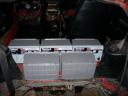
This gets the batteries further away from the engine in the back, which could cause issues due to heat. A battery is basically just an ongoing chemical reaction, and the speed of this reaction is proportional to the temperature. Batteries can produce more current when warm, which is normally a good thing (this little fact is exploited by EV dragsters), but if 1/2 of the pack is at 100*, and the rest of the pack is at 50*, it could lead to serious battery equalization issues. This arrangement avoids this issue by placing them in the main compartment, but also puts their center of mass up higher than is ideal. This could lead to excessive body roll in corners. It does also place them much closer to the center point of the vehicle, directly between the wheels, which would lead to faster steering response. I guess its all about trade-offs.

Battery Placement 2
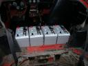
This arrangement allows for 5 instead of the previous 4 in the passenger compartment. This means I can upgrade from 144v (12) to 156v (13), which should increase range and acceleration about 8%, at the expense of 60lbs.

Battery Placement 3

Same thing, except the batteries are slightly closer together, but the terminals are more exposed. This should make mounting easier, but I will need a lexan cover to keep hands away from the lethal voltages present.

1000Amp Motor Controller

March 20, 2008

Here it is, the 1000A monster:

1000Amp Motor Controller1000Amp Motor Controller 21000Amp Motor Controller 3

I’m worried about melting my motor with this beast. Or grenading the transmission. 1000Amps is alot of juice.
156volts x 1000amp = 156000watts

156000watts / 750 watts/hp *.80 efficiency factor 166hp peak

I will be running it at 144v at first, so it will be 144,000 watts, or 157hp.

Battery Balancer Components

March 18, 2008

I received all the components for the battery balancing system today.  This setup is necessary to ensure that each battery is well cared for. It will intergrate with the charging microprocessor to halt phase 1 of charging (bulk stage) as soon as a preset voltage level is exceeded. This indicates that at least one cell is beginning to reach its maximum capacity. It will also monitor the pack temperature and abort charging if anything fluctuates out of a safe range. At this point the charger’s computer will signal to the balancing system that equilization may commence. The balancer will then systematically bring each individual cell up to a full charge, as well as taking care of phase 2 (absorption) charging and phase 3 (float) should it be necessary.

Relay BoardsRelay Boards 2Relay Boards 3Relay Board

The relay boards will allow the balancer to select, charge, and monitor each battery individually. I have 16 outputs available, 12 of which will be used for the traction pack (possibly 13 in the future should I upgrade to 156volts), 1 for the 12v accessory battery, and 1 for the control of the balancer charger. This leaves 1 output for future implementation.

Odyssey UltimizerOdyssey Ultimizer 2Odyssey Ultimizer 3

The Odyssey Ultimizer is specifically designed for the unique Hawker AGM chemistry. I chose the 12amp version so I do not melt my balancer relays (rated for 15a max).

Dios Processor

This microprocessor will be the heart of the system. I plan on interfacing it to the charger’s status LEDs via optical photoresistors. It has 16 digital I/O and 6 analog inputs, perfect for this application.

Generator Aquired

March 17, 2008

A generator has been acquired. It is capable of 10,000 watts at either 120 or 240volts. It is belt driven which should give me much more flexibility in mounting options. Is also fits well with the modular theme; it could be removed and replaced easily with a different unit as long as the pulley is compatible.

10,000 Watt Generator

Plugging some quick numbers into the incredibly handy EV Calculator I see that the a 10kw output should be capable of sustaining a cruising speed of 65mph on perfectly level ground. In this scenario the batteries will be used only for additional load (incline, headwind, increased speed), and they will receive the surplus output when load decreases (downhill slopes, tailwind, decreased speed).

If I then extrapolate this with data available on diesel generator fuel consumption, which appears to be 210-240 grams fuel per kWh. Therefore 1 hour at 10kw will consume 2400 grams = 5.3lbs of diesel fuel. Diesel weighs about 7.2lbs per gallon, so this equates to .75 gallons of fuel to achieve 65 miles.

Battery Layout

March 16, 2008

Because the diesel generator will be occupying all of the available space in the rear hatch, all 12 batteries must now fit under the hood. This took alot of wiggling and measuring, but I think I came up with a layout that will work well. This has the added bonus of using as little of my precious (and heavy…) 4/0 cable as possible.

Battery Arrangement OptionsBattery LayoutBattery Mounting

I also completed the removal of the rear hatch sheet metal. Most of this space was previously for the fuel tank and the spare tire well. The diesel should fit here very nicely.

Cutting Sheet MetalRear HatchRemoved Portion

Motor to Transmission Adapter Plate

March 16, 2008

In order to mount the electric motor to the existing transmission a plate needed to be fabricated.

Boltpattern TracedTraced CompleteDrillingDrilling Progress

To make the center hole, which will allow me to mount the plate to the transmission in order to get an exact center for the motor mounting holes.

Center Hole Drilling Platform

The 2″ hole was simply drilled in with a hole saw in a hand drill. Lots of lubricant (WD-40) was used, as well as a slower speed and lots of breaks. Aluminum is very easy to work with compared to steel. The plate is .500″ thick 6061. A 12″x13″ piece cut and shipped cost $80.

Adapter Plate MountedMotor Adapter Plate Center

Close enough…

I have ordered a part made which will connect the shaft from the electric motor to the splined shaft on the transmission. It will be fabricated in part using the old clutch. Any further progress mounting the motor must wait for this.

Engine Tear Down

March 16, 2008

L24 240z Engine
In order to fund the conversion, as well as a learning experience, I tore down the original engine piece by piece.

L24 Disassembly

The components were sold.

SU Carbs

L24 Disassembly Cont.

Finally, we are left with a bare engine block.

Bare L24 Block

All in all I made enough to pay for the purchase of the electric motor. Seems like a fair trade to me…..

Cable Making

March 16, 2008

Many hours were spent making battery cables. One must ensure that the cable is completely inserted into the copper lug before it is crimped. A good connection is essential, as any chain is only as good as its weakest link, a chain of 12 batteries has about 48 critical points ((battery terminal to copper lug, battery lug to cable) x 2 per battery)

Measuring 4/0 CableJumper CableThe Shortest Distance Between Two Points…

Each wire needed to be as short as possible, but the lugs were too long to go straight between terminals. This arrangement requires very little cable, and therefore the smallest amount of electrical resistance possible, to connect the batteries.

Completed Battery Interconnects

The batteries sit on 3/16″ mild steel 2″ angle. This will be welded to the frame as soon as the motor is in place comfortably.

Electric Vehicle Drivetrain

March 16, 2008

My powerplant:

Kostov 9″

A kostov 9″ series wound 144v electric motor. Rated for 107A continous. It weighs approx. 100 lbs yet can produce several hundred ft. lbs. of torque.
12 Hawker Odyssey 73ah AGM Batteries Arrive

These 73ah AGMs are rated to produce 1750 amps for 5 seconds, or around 70 amps continuously for one hour. They weigh 60 lbs each, with a combined pack weight of 720lbs. The total pack capacity is 10.5kwh. Their peukert’s factor is extremely low, so they deliver their full capacity to the motor very effeciently. They are also capable of being charged to 90% capacity in just half an hour, or less, if you could provide enough current. A typical 110v 15a plug will take more like 5 or 6 hours. They are rebadged by sears and sold under the “DieHard” brand as “Platinum”.

4/0 Gauge Battery Welding Cable

The roll of 4/0 gauge cable arrived. This stuff is heavy! I had it printed with “DANGER – High Voltage”. I also received orders of 4/0 gauge copper battery terminal lugs, and 1.1″ diameter heat shrink lined with a corrosion preventing sealant.

4/0 Gauge Cable Size Comparison

400 Amps continuously….no problem.

Electric Vehicles Just Make Sense

March 16, 2008

90% of my driving is the same route, every day. I commute to school each day, 24 miles each way. The drive takes me about 25 minutes and costs me about $6 a day in fuel at todays gas prices. This is with and “fuel effecient sedan” EPA rated 32mpg highway. If you factor in oil, tires, maintenence, and the depreciation over time of the vehicle each mile may cost considerably more than this.

If I can achive this commute each day using readily available (cheap!) electrons, I stand to save a considerable amount on fuel. I spent $2300 on a pack of 12 PC1750 Hawker Odyssey sealed AGM batteries that are warrantied for 4 years free replacement. Assuming the pack lasts only those 4 years, my battery costs are $575 a year. When you add electricity to this ((5 recharges/week X 52wks) X 10kwh/charge X $0.10/kwh) = $252 in electricity “fuel” costs. This makes driving electric around half as costly as driving an ICE vehicle).

Oh, and its clean, fast, quiet and fun.

Out comes the engine…..Out with the old…

Project AmpEater, the electric 240z

March 15, 2008

Day 0 – The stock vehicle. It isn’t going to stay that way for long….

Stock 240z


Design a site like this with WordPress.com
Get started